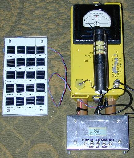
Solar Powered CDV700 with CARL box and yellow power LED. (not original meter)
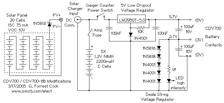
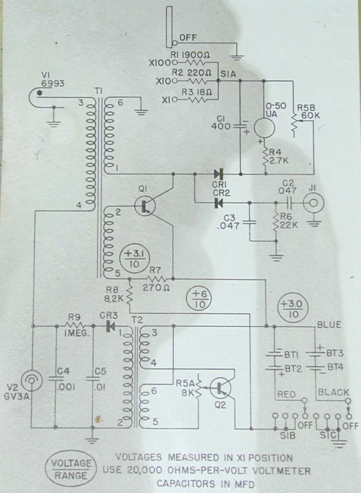
Schematic of CDV700 modifications.
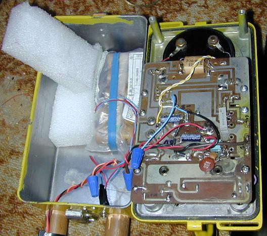
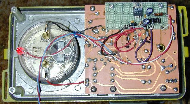
CDV700 wiring to rechargeable battery, battery jack and CARL counter box.
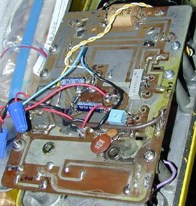
View of the CDV700 PC Board, note the plastic washers on the board mounting holes.
Introduction
This project involves making several modification to an early 1960s era Victoreen CDV700 or CDV600-6B geiger counter. These counters are available on E-Bay for around $50 to $100. The modifications use modern electronic parts to improve the counter’s stability, extend the run time, and add a solar recharging capability. Circuit modifications include:
- Conversion to a single 5-cell NiMH rechargeable battery pack.
- Adding a voltage regulator to the geiger counter’s main supply.
- Adding a secondary voltage regulator to the 3V supply.
- Adding a front panel LED power indicator.
- Adding an external power input jack for charging the battery.
- Adding a small solar panel for charging the battery.
- Reducing the radio emissions from the geiger counter’s oscillator circuit.
The upper photos are from a CDV700 counter with only some of the modifications, the lower photos are from a CDV700-6B counter with all of the modifications.
Reviving a Dead Geiger Counter
This particular CDV700 meter required a lot of repair work to make it functional. Here are my notes the repair operation.
Modifications
Battery Conversion
The original power supply for the CDV700 and CDV700-6B uses two pairs of D cell batteries. The 3V-6V battery set supplies the oscillator circuit with 33ma of current when properly adjusted. The 0V-3V battery set supplies the detector circuit with a few ma of current. This causes the batteries to wear out at different rates. Conversion to modern NiMH C cells allows the counter to run for longer periods of time. The rechargeable batteries work well with a small solar panel for recharging. A set of 5 AA-size NiMH cells would also work for this application. NiCd cells can also be used, but NiMH cells have higher power density and are less toxic.
Voltage Regulation
The low dropout voltage regulator stabilizes the voltage to the counter, providing a consistant power supply voltage as the battery discharges. This should improve the counter’s calibration stability. The five NiMH cells provide an output voltage in the 6-7V range. The LM2950T-5.0 regulator circuit produces 5V, the 1N4001 diode raises the ground reference of the LM2950T-5.0 up by 0.7V, making the regulator’s output 5.7V. The 10K resistor is used to add 0.5ma of current flow through the 1N4001 diode for the purpose of stabilizing the diode’s voltage drop. The string of diodes across the 0-3V terminals is used to stabilize this half of the supply at around 2.7V. This half of the circuit only requires a small trickle of current, the upper half of the circuit uses about 35 ma. The diodes absorb the extra current and make single supply operation possible. The two 100uF 16V electrolytic capacitors are used to isolate any AC instabilities between the two halves of the power supply.
Front Panel LED
The front panel LED circuit uses some of the excess current from the 0-3V half of the supply. This is essentially “free power”, that is otherwise wasted in the diode string regulator. The series resistor limits the LED current to around 20 ma.
Solar Panel Charger
A small solar panel was built for charging the NiMH battery. It consists of 20 individual solar cells on a circuit board with a plexiglass shield. This is a non-standard assembly, a suitable substitute can be made with single or multiple small solar panels that are sold in the electronics hobby market. The solar panel should put out between 8 and 10 volts DC in full sun, it should be capable of feeding 50 to 100 ma of current through the NiMH battery. The series 1N5818 schottky diode prevents reverse flow through the solar panel at night.
Oscillator RF Reduction
The original CDV700 and CDV700-6B circuits produce RF ringing on the high voltage oscillator’s transformer drive circuit. This can be greatly reduced by adding a 1.5nF (CDV700) or 2.7nF (CDV700-6B) capacitor across the oscillator driver transistor’s base and collector leads (V4). This capacitor sets the oscillator into a critically damped switching mode to produce a cleaner square wave signal.
Construction
Battery Modification
First, remove the six screws that hold the two white plastic battery holders on the back of the circuit board assembly. The original screws should be replaced by shorter screws, 3/8" long 6-32 thread machine screws will work, you may need shorter screws. The screws on the probe-wire side of the counter are adjacent to a high voltage circuit board trace, place a nylon washer between the screw and the top of the board to prevent grounding or arcing of the high voltage line. Note where the original battery wires connect to the board, you can find the 0V, 3V, and 6V contacts on the circuit board this way. Mark the voltages on the board with a magic marker. Unsolder the old battery wires. The new battery assembly and fuse will go in the bottom of the geiger counter box. I wrapped my new battery in a thick plastic bag and used heavy packing foam to wedge it into the bottom of the case. Be careful to keep any battery wiring from poking through the plastic and touching the metal case. A second piece of foam was cut to fit between the counter’s meter and PC board, it keeps the battery from moving vertically. Drill a hole in the back of the counter box for the DC power connector. Wire the two battery wires to the power connector, and add two more wires that are long enough to go from the connector to the board assembly. Make the wires long enough that the top half of the counter can sit upside down next to the bottom half. The battery (-) lead should go to the old 0V wire position on the PC board, the battery (+) lead goes to the original +6V position, it is one of the rotary switch contacts.
CDV700-6B with regulator board and LED on meter, the regulator board is mounted above the original board with 1/4" plastic spacers.
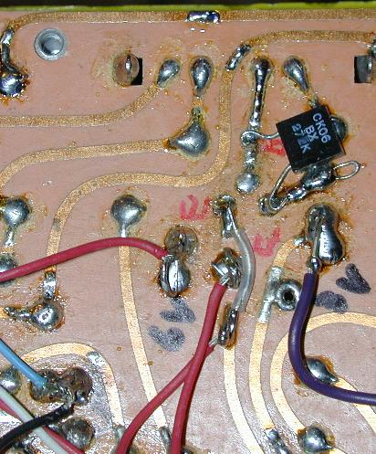
Close-up photo of the CDV700-6B PC Board, note cut power switch traces, teflon insulated jumper wire, and added oscillator capacitor.
Voltage Regulator Addition
The geiger counter power switch contacts are part of the rotary switch, it is necessary to isolate the +6V switched lead in order to insert the 5.7V regulator circuit. The switch contact that is clockwise (from the back side) from the +6V position is the switched contact. The switched contact in the CDV700 connects to a thick circuit board trace, use an Xacto knife to isolate the switch contact. In the model 6B, the switch contact has two traces running in oposite directions, cut both traces with an Xacto knife, and route around the switch contact. Assemble the voltage regulator IC, the two 100nF capacitors, the string of diodes, the 10K resistor, the 1N4001, the two 100uF capacitors, and the 91 ohm resistor on a small piece of perforated board. The board was hand-wired on the back side with bare wire. Loops of hookup wire were fashioned on the edge of the perforated board for connection to external wiring, this make it easy to add or remove the wires. Stranded wire was used to link the regulator board to the counter board. The board was mounted on two of the original battery holder holes using 1/4" insulated standoffs and 6-32 thread screws. Bring the following signals from the regulator board with stranded wires: -battery power, switched +battery power, 2.7V, 5.7V, and LED +/-. The regulator + input connects to the switch contact with the cut traces. The regulator 5.7V output connects to the other side of the cut trace or traces. The regulator - input connects to the 0V trace on the board. The regulator 2.7V output connects to the 3V trace on the board. Note that the regulator board will not produce the 2.7V power unless it is connected to the rest of the CDV700-6B circuitry. The CDV700-6B oscillator adjustment potentiometer (marked HV) should be adjusted so that the battery current equals 33ma. The current can be measured by turning off the counter and placing the ammeter across the power switch contacts, this powers up the circuit without the need for cutting the circuit wiring.
Power LED Addition
The LED + and - lines go from the regulator board to the remote power LED. The LED can either be epoxied into a small hole in the front of the case as shown in the CDV700 photos, or filed flat and epoxied onto the top center edge of the meter’s back side for an eerie red glowing effect, this is shown in the CDV700-6B photo. A high intensity LED works best for mounting behind the meter.
Oscillator RF Mod
Solder a 1.5nF (CDV700) or a 2.7nF (CDV700-6B) capacitor across the base and collector of the oscillator transistor. The CDV700 photos show two parallel disk capacitors mounted on the back side of the board.
Parts
- 1X LM2950T-5.0 low dropout 5V voltage regulator
- 1X coaxial battery power jack
- 5X 1.2V NiMH C cells, 2200maH (or high capacity NiMH AA cells)
- 1X 1 amp fuse
- 2X 100nF capacitors
- 4X 1N4001 Silicon Diodes
- 3X 1N5818 Schottky Diodes
- 1X 91 ohm 1/4W resistor
- 1X red high intensity LED
- 2X 100uF 16V electrolytic capacitors
- 1X coaxial battery power plug
- 1X solar cell array, VOC: 10V ISC: 75ma (or similar)
- 1X 1.5nF capacitor (CDV700)
- 1X 2.7nF capacitor (CDV700-6B)
More Information
See George Dowell’s notes on modifying a CDV700-6B counter.
Schematic of the CDV700-6B counter.
Sources
- Forrest Cook http://www.solorb.com/elect/