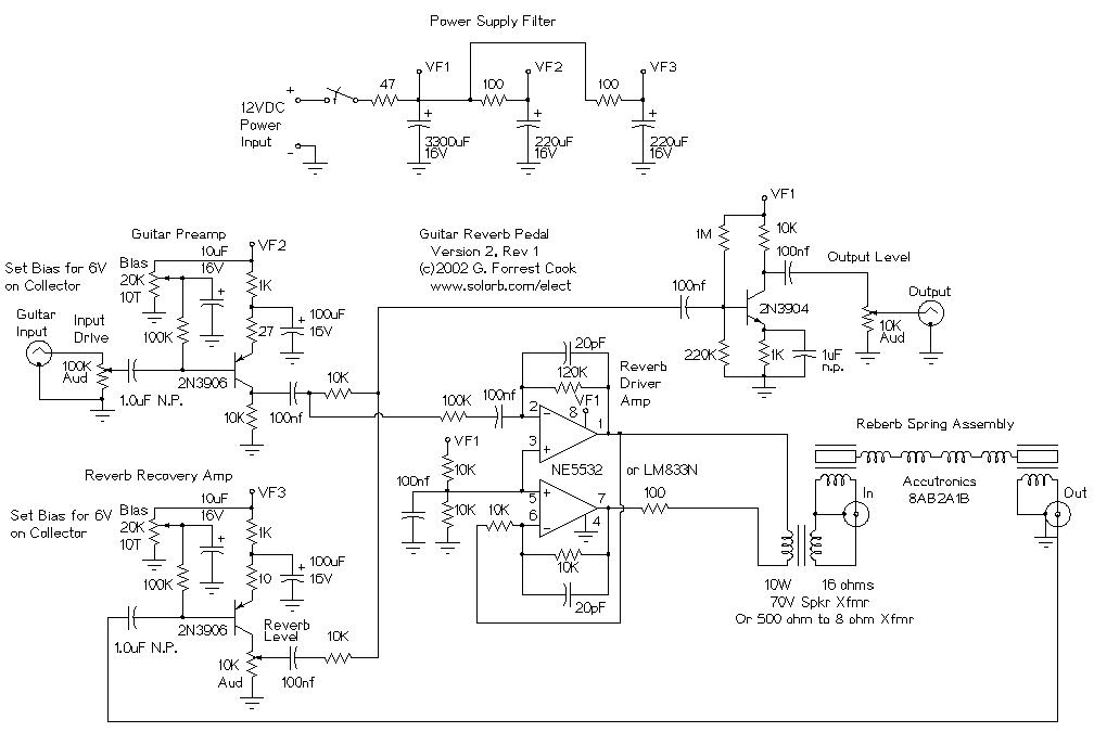
Introduction
This is my second-generation guitar reverb circuit. The output may be too high for a guitar amplifier input, try putting a 1K to 10K resistor between the output 2N3904 transistor’s emitter and the 1K/1uF junction to reduce the gain.
Specifications
Nominal battery voltage: 12V
Theory
Not finished The transformer is a standard “70 volt” audio line transformer that is often found on PA systems. The transformer adapts the dual op-amp output impedance to the reverb driver coil impedance. It also serves to isolate the ground on one side of the reverb coil from the op-amps. Without the transformer, one of the op-amp outputs may be shorted to ground at the reverb case. Some reverb tanks may not require the transformer, you may need to put a ground-isolated connector on the input.
Alignment
The two 2N3906 stages need to have the bias set manually for the least distortion. With no signal input, adjust each pot so that the corresponding collector is at 6V. You may further tweak this adjustment for minimum distortion at high input levels.
Use
Plug the guitar into the input. Adjust the input drive level for minimum distortion. Adjust the output level for minimum distortion. Adjust the reverb level for the desired amount of effect. Play some surf music.