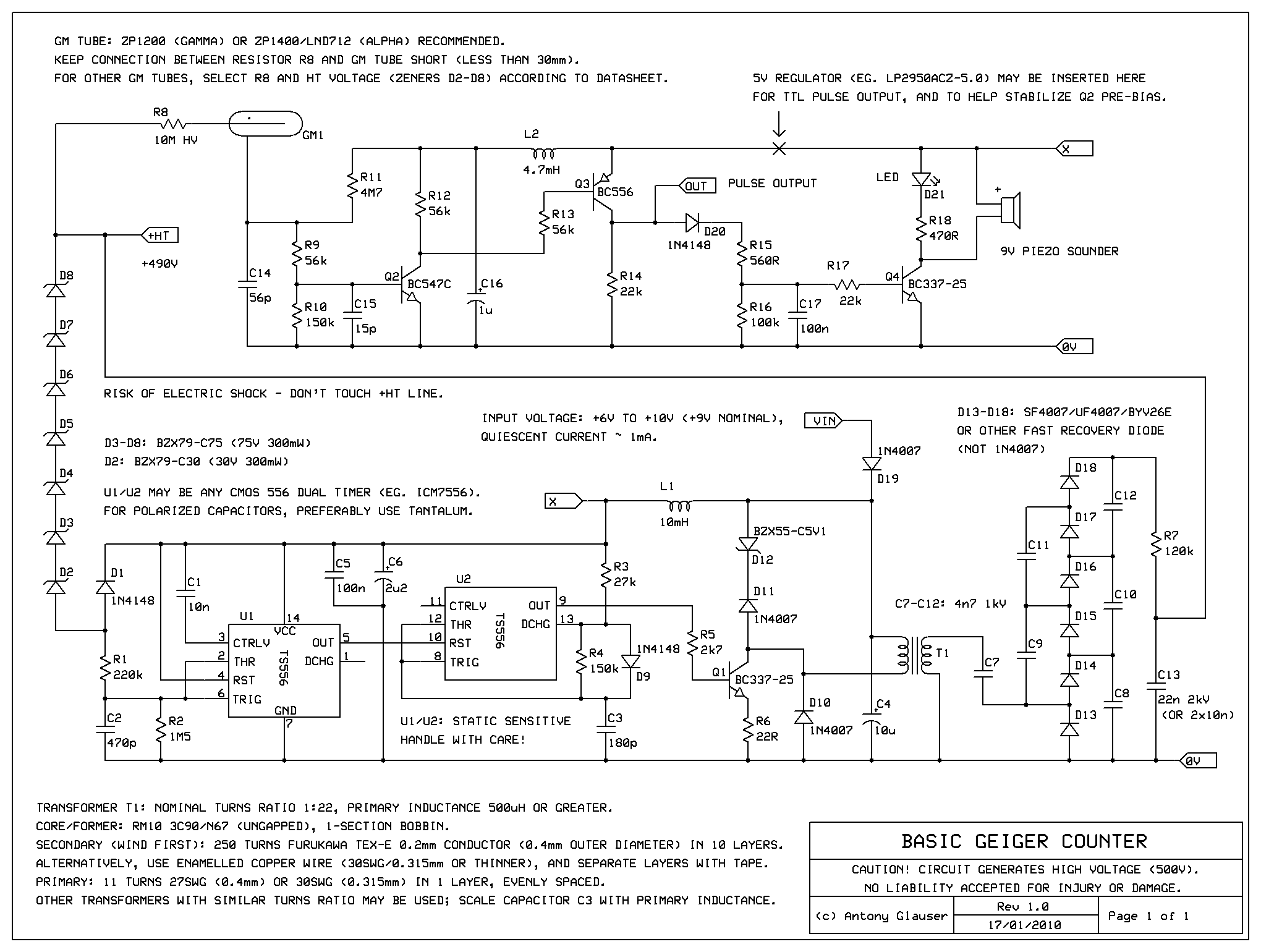
A basic Geiger counter circuit
Geiger counters are available in all shapes and sizes, but they tend to be quite expensive to buy (typically a couple of hundred US dollars for a simple model, rising to a thousand dollars or more for a professional instrument). Building your own can be a very rewarding alternative.
The only bit that is unavoidably quite costly is the Geiger-Muller tube itself - expect to pay 50-100 US dollars. Roughly speaking, the more you pay, the larger the tube, and the better (more sensitive) the counter will be. Personally I wouldn’t bother with any tube smaller than an LND712 (ZP1400), unless I was on a very tight budget, or only interested in detecting relatively high levels of radiation. An LND712 will pick up small radioactive items such as watches & minerals quite easily. The GM tube is a specialist item, so unlikely to be in your standard electronics catalogue. However, many manufacturer-suppliers will accept individual one-off credit-card orders. I have bought tubes from LND Inc. in the US, and Alrad Instruments in the UK, for example.
The basic Geiger counter consists of (a) a low-current (<100µA), high voltage power supply, (b) a pulse detector circuit, ideally matched to the tube time-constant and (c) whatever you want to attach to the output by way of clicks, beeps, flashes, dials, digital counters or alarms. You can find a number of home-brew circuit designs on the web, many of them very good. The circuit shown in this article has undoubtedly borrowed from them. It is primarily designed for reliability and tolerance to component variations. I have built many versions of this circuit, and none of them have ever failed to light up first time, nor have any of them ever gone dead on me.
Geiger-Muller tubes
GM tubes come in different sizes and types. The LND712 (ZP1400) is probably the most widely used in small pocket-sized instruments. It is about 45mm long and 15mm in diameter, with a thin mica end window to allow it to detect alpha and beta particles. All tubes can detect gamma rays to a greater or lesser degree, depending on their geometry. The small size of the end window means that it is relatively robust; larger, ‘pancake’ style tubes are much easier to break. (Don’t be misled by the solid, heavy feeling of the iron body in these types - it’s quite soft! Clamping the tube with too much force will over-stress the window, causing it to split). In all cases, it is advisable to cushion the tube in the instrument with a thin layer of foam, and to avoid putting too much force on any one part of the body. The LND712 is best fixed down with a pair of thin cable ties, placed some distance away from either end. Also, don’t solder directly to the body, or any connections where a separate clip is provided (e.g. the anode pin of the LND712). Applying heat near to the glass-metal seal will cause it to break and let air in.
Detecting alpha/beta vs. gamma
Briefly, GM tubes that can detect alpha & beta particles do so very efficiently - up to 100%. Gamma detection is much less efficient; only a percent or two of the photons passing through the tube will set it off. If you’ve got a tube that detects both, putting material in front of it will tell you which you are picking up. If it’s alpha particles, which are easily blocked, the counts will stop with a sheet of paper. A few layers of tin-foil will be needed to stop beta. If it’s still going after that, it’s gamma. By the same token, an alpha-sensitive tube will give you a much higher reading than a gamma-only tube for a given lump of material that kicks out both alpha and gamma (most do). A small lump of uranium ore that makes a gamma counter chatter will cause an alpha counter to roar; definitely more exciting.
So why would anyone bother with gamma-only tubes? Firstly, it’s easier to make a sturdy instrument for use in wet or dirty environments, because you don’t need to cut any holes in the case to let the alpha particles into the tube. (The same hole will also let water into your circuitry, which will helpfully ‘detect’ it by shorting out). The second point is to do with the fact that gamma rays are more penetrating, so they can reach your detector from all the way inside a lump of rock, while you can only detect alpha particles being emitted from the surface of the rock. A thin crust of mineral on an inert lump of rock will give more or less the same alpha reading as a big, rich lump of ore, while a gamma-only counter will readily discriminate between the two. This is more useful if you are trying to get a quantitative reading of how much active material you’ve got. It’s also a bit easier to estimate dose rates.
Of course, putting a shield in front of an alpha sensitive tube makes it gamma-only, so you can get the best of both worlds, especially if you can make your optional cover properly waterproof at the same time.
Circuit overview
The circuit below is designed to achieve low power consumption - less than 1mA - for extended battery operation, while being relatively stable and easy to build. None of the component values are especially critical, and it is possible to use other transformer designs. For best efficiency, the value of oscillator capacitor C3 should be adjusted to resonate the transformer. If you don’t have an oscilloscope available to help you with this, you can get a fairly good result by scaling up C3 roughly in proportion with the primary inductance. You can estimate this from the quoted specific inductance of the core, multiplied by the number of primary turns squared. The transformer is probably the trickiest bit to make, but it’s worth doing well. You may struggle to find suitable commercial parts with this turns ratio, although it is just about possible to press a small mains transformer into service by using it in reverse. The efficiency will be fairly low, though.
Disclaimer: Readers who attempt to build this circuit do so entirely at their own risk. If you touch the high voltage line after the circuit has been energized, you will get an electric shock. Note that energy is stored in the capacitors even after power is removed. Before working on the circuit again, discharge them by shorting the +HT line to ground (0V) through a large resistor (>1M). Don’t hold the shorting resistor in your fingers or in a pair of metal pliers - glue it to an insulating handle, e.g. an empty plastic pen tube.
Circuit description
U2 is a standard 555 astable oscillator, built using a dual CMOS version of the chip for lower current consumption and faster switching than its bipolar counterpart. It generates pulses with a duration of about 3.5µs and repeat rate of 45kHz, as determined by R3, R4 and C3. The inclusion of D9 permits a mark-space ratio of less than 1:1. Each pulse drives Q1 briefly into conduction, which in turn draws a gulp of current through the primary of transformer T1 and sets it ringing. (The parallel inductance of the transformer resonates with the parasitic capacitance of the secondary winding). D10-D12 and R6 are included to help protect Q1 against excesses of voltage and current that may occur at various points during the oscillation cycle, especially if the transformer is not ideal. They can probably be left out, with the emitter of Q1 connected directly to 0V.
C7-C12 and D13-D18 form a three-stage Cockroft-Walton multiplier, which rectifies the output of T1, generating up to three times the peak-to-peak voltage of the secondary waveform when the capacitors are fully charged. Resistor R7 combines with the reservoir capacitor C13 to act as a low-pass filter, limiting the high frequency ripple on the +HT line. If the oscillator U2 were to run freely, the GM tube would see the full +900V output of the multiplier and be damaged. However, as the +HT line approaches the desired tube operating voltage (+490V), zener diodes D2-D8 begin to conduct, passing a small amount of current into C2 via R1. D1 sends any excess current back into the +9V supply line, to protect the input of U1 from being over-voltaged. U1 serves as a Schmitt trigger, generating a clean switching signal to deactivate the oscillator U2 for a minimum period of time determined by R2 and C2. A quick calculation shows that even at full load, the +HT line will drop by only a few volts before the oscillator can cut back in again. At lower loads, the +HT voltage decays more slowly, and the zeners remain in conduction for longer. Under these conditions, U2 only operates for short bursts, so that the average current drain is very low - typically 1mA or less.
C14, C15, R9 and R10 form a passive pulse-shaping circuit that is approximately matched to the ZP1200 tube time-constant, as per the manufacturer’s data sheet. Most of the pulses will be quite sufficient to switch on Q2 without any pre-bias. However, R11 ensures that any pulses falling just below the 0.6V switching threshold of Q2 will be counted too, without significantly increasing the susceptibility to noise. Inserting a series regulator in the supply line will fix the threshold level, so that it won’t vary with battery voltage. Note that the output from the tube could instead be sent into a high-pass filter circuit to help separate out overlapping pulses when they occur, but the simpler design shown here was chosen with the philosophy that if the tube is conducting, Q2 should be on. (The high-pass filter edge detection method is a little more complicated to implement, and under high field conditions there is a risk that the apparent count rate will begin to drop, when in fact the tube is beginning to saturate. If you are unfortunate enough to be present under these circumstances, at least with this design you will know because the LED will be on and the piezo will be sounding!)
Q3 buffers and inverts the output of Q2 to give a positive-going output pulse for further processing. Components D20 to R17 extend the length of the pulse, so that the LED flash is long enough to appear bright to the eye, and the piezo sounder beeps rather than clicks. The value of C17 can be varied to adjust the duration of the audio-visual signal as required.
D19 is included to provide protection against accidental reversal of the supply voltage. C4 prevents the current pulses drawn by Q1 from appearing on the +V supply line as ripple. Choke L1 combines with C5 and C6 to remove any residual fluctuations from the rail supplying U1, U2 and the pulse detection circuitry.
The circuit should run OK down to a supply voltage of about 6V. It is also capable of supplying enough current on the HT line for several tubes, e.g. if you want to try making a muon telescope, or a cosmic ray detector. Any number of additions can be made in order to improve its functionality. The two most obvious options are
- Connection of the pulse output to a digital counter, or ’totalizer’. This is usualy very straightforward, but check that the maximum response frequency of the counter is more than a few kilohertz, and be sure to clip the pulse height using a resistor and some series diodes or a zener, if necessary. (Many totalizers require a 3-5V supply, and their inputs are rated accordingly). The output pulse length from the Geiger counter circuit will typically be 150µs; this should be sufficient to trigger most totalizers reliably, otherwise you can adapt the LED/sounder drive circuit to extend the pulse length. Note also the polarity of the required trigger signal - you may need to add another transistor buffer stage to invert it.
- Addition of an analogue meter. The proper way to do this is to feed the pulse output into a single-shot monostable based around another 555, to produce pulses of a uniform length which can then be low-pass filtered to give a DC voltage that is linearly propotional to the count rate. Varying the duration of the monostable pulses will alter the range of the meter. For a simpler, less accurate output, you can get away with omitting the monostable.
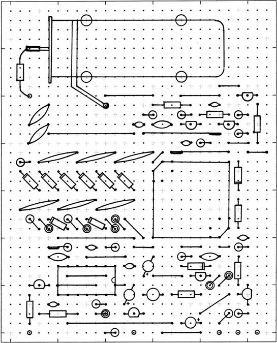
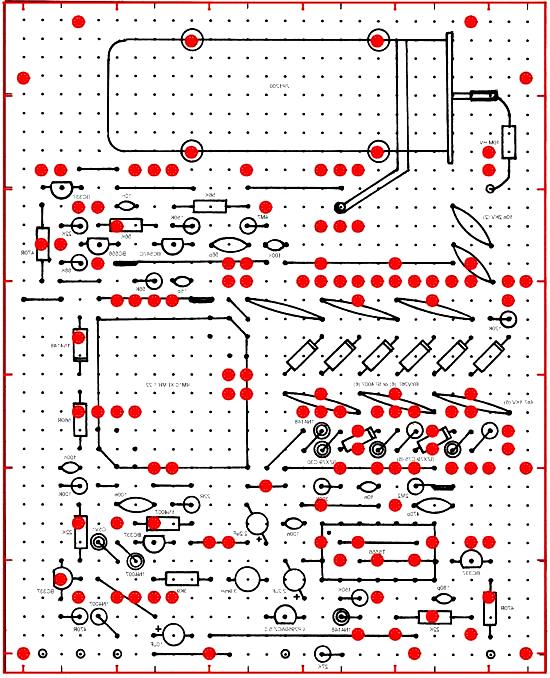
Circuit layout
Circuit layout is not especially critical, but avoid putting the sensitive pulse detector circuitry (Q2) near to the transformer. A suggested component plan for building the circuit on a piece of stripboard 76mm x 91mm is shown below, along with a mask for cutting the tracks on the copper side. (The red spots indicate where you should cut the tracks - a 3-4mm drillbit works well for this). Note that the laid out circuit is very slightly different from the above schematic:
- A low-power three terminal regulator (LP2950ACZ-5.0) has been inserted just downstream of the 10mH choke, so that all of the +V line is at 5V. You can skip this if you like, it’s not really necessary.
- The pulse output is buffered with a simple open-collector circuit, consisting of a BC337 transistor driven through a 22k base resistor, with a 470R current limiting resistor on the collector.
- Pin 5 of U1 is similarly buffered, so that the duty cycle of the oscillator can be used to check the health of the HT supply (and hence the battery).
A few other points to be aware of:
- The copper tracks (not shown) run vertically in these images, i.e. north-south.
- Where a wire connection is shown with double thickness, as occurs in three places, the wire is folded back under the board to connect two adjacent tracks together.
- An inner ring drawn on a diode mounted vertically indicates that it is pointing ‘up’, i.e. with the cathode end furthest from the board.
Component identities aren’t marked, but hopefully it should become fairly obvious following a bit of detective work with the schematic.
 |
 |
Winding the transformer
This is definitely the hardest part of the whole process, if you’re a perfectionist. There are a couple of things to consider.
Firstly, getting enough turns inside the available space is easiest if you wind them in an orderly fashion, i.e. side by side. This is tricky to do by hand. You could opt to use a thinner gauge, so that the same number of turns takes up less space - but then it’s easier to break the wire in the process. (It also increases the winding resistance, not that this matters too much in a low-current application). I found that for this type of job it’s worth investing the time in rigging up a small, low speed electric motor with a spindle that fits the former, so that you can leave the motor to do the turning and concentrate on feeding the wire in neatly.
Secondly, if your transformer is likely to see a couple of hundred volts inside it, you have to start worrying about the strength of the insulation on the wire. Ideally, each layer in the secondary winding would only see a few tens of volts difference between itself and the next. However, in practice it’s hard to guarantee that a wire near the end of the winding won’t slip down the edges of the former, and find itself next to one near to the start. If you’ve inadvertently scratched or otherwise weakened the very thin enamel coating, breakdown could eventually take place between the two, especially if the counter is working in a hot or humid environment. Impregnating the finished winding with lacquer may help to reduce the likelihood of degradation, but it’s better to avoid the problem altogether by separating off layers of turns with transformer tape. You don’t necessarily have to tape every single layer, although this is best if you have the patience.
My preference is to opt for a really fool-proof alternative solution: use double or triple insulated wire, which has a voltage rating that far exceeds anything that is likely to be generated in the transformer. This is basically wire with multiple layers of polymer coating on it; wire with its own built-in transformer tape, if you like. It’s a lot thicker for the conductor size, so you won’t get as many turns on, but the end result works fine. You just have to use a higher oscillator frequency to keep the primary magnetization current acceptably low. It’s comparatively expensive, but worth it for the satisfaction of knowning your transformer won’t fail, and that you can reuse it for a higher voltage application later on (e.g. a flyback circuit).
Having said that, I’ve made up several units where the transformer secondary consists of thin (0.15mm) ordinary enamelled wire, bunch wound on a smaller RM8 former, and never had any problems yet. If you’d prefer to try this instead of the Tex-E design, you should find that you can get about 650 turns for the secondary, leaving space for 33 turns of 0.28mm primary to maintain the turns ratio. The higher primary inductance needs a larger timing capacitor C3 to resonate it - 820pF for 4.5mH worked fine.
Images of completed units
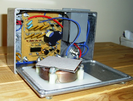
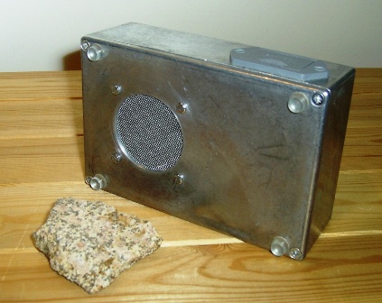
A simple prototype alpha counter using a ‘pancake’ type tube is shown below. The tube mounting method is not ideal - stiff solder tags on top of the posts hold the tube in place, and some glue has been added for good measure. A solid plate with a layer of foam would have been better, but space was a bit tight in this box. The square cardboard sandwich on the back of the tube contains a copper foil electrostatic shield to block the field from the high voltage generator circuit, which otherwise triggers the detector circuit and causes the counter to bleep rather alarmingly!
 |
 |
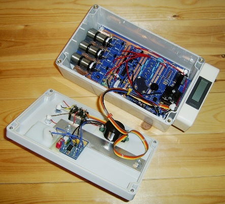
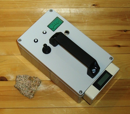
A slightly more complicated gamma-only counter is shown in the next two images. It uses three ZP1200 tubes for greater sensitivity, but essentially the same circuit as shown in this article to drive them. A single larger tube could have been used instead, but this would have worked out more expensive. The arrangement shown also offers a degree of redundancy against tube failure. There is a marginal technical justification for using multiple tubes, too. Due to the ‘dead time’ effect, a single tube is unable to respond for 200µs or so after an event; this distorts higher count rates, and limits the maximum achievable. Three smaller tubes, each of which triggers less often, can reach a higher overall maximum - not that I would really want to be present under these conditions. An analogue meter gives a quick visual indication of the count rate. A digital pulse counter has been added to allow more sensitive detection of subtle background variations. The case is entirely waterproof when closed, so the unit can be used in wet conditions.
 |
 |
A short note about counting statistics
A question you may find yourself asking is, how do I know whether a higher reading is significant or not? Roughly speaking, the uncertainty in a given count is equal to its square root. If you add up the clicks from an LND712 over a minute in a low background area, you’re most likely to get around 16 counts. If you see 19 counts the next minute, this isn’t statistically significant. If you get 40, it probably is - but you’d be wise to take a few more readings to be sure.
Equally, you could simply count for longer. Over a four-minute period, you’d expect to see 64 counts, giving you an uncertainty of 8 counts. But notice that 4 counts is 25% of 16 counts, while 8 counts is only 12.5% of 64. So by counting for longer, you’re reducing your percentage uncertainty, and therefore improving your ability to resolve differences. The same reasoning should also show you why buying a larger tube (which gives more counts per minute for the same radition level) is worthwhile, if you want to be able to detect small variations without having to wait for ages.
Other detector types
The Geiger-Muller tube is exquisitely sensitive for its cost and size. An ionization avalanche in a rarified argon atmosphere, driven by the electric field in the tube, amplifies the initial event by an enormous factor. However, the drawback of this is that every particle produces the same size pulse, regardless of its energy. If you know the energy of the particles you’re measuring, e.g. because they come from a particular isotope, then you can calculate a biological dose rate. If you don’t, then you might be out by a factor of a hundred or more. The solution is to use a detector that can resolve individual particle energies, e.g. a photomultiplier with a scintillator, or one that measures the average energy deposition over time, such as an ion chamber. The humble photodiode can be put to use for this purpose, albeit with very limited sensitivity.
There are designs and schematics out there on the web for home-brew versions of these instruments, but it’s probably fair to say that the Geiger counter achieves the best combination of sensitivity, reliability, cost and ease of construction. They’re still widely used, and they haven’t really changed much in the hundred or so years since they were first invented.