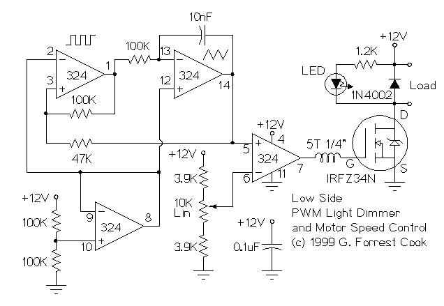
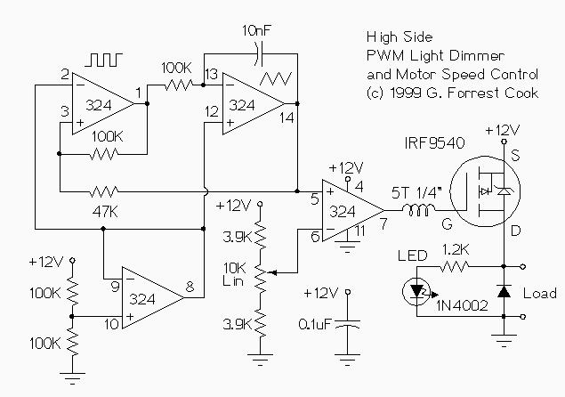
The diagrams are for 12V operation only and there are high side (common ground) and low side (common +12V) versions. The low side version is in fact, identical to the original circuit when wired for 12V operation. The low side version allows the use of higher power and more inexpensive N Channel FETs, whereas the high side version, which uses P Channel FETs is used where common ground load wiring is a requirement. The inductor on the gate side of the power MOSFET transistor can be a ferrite bead or a few turns of wire wrapped around a 10 ohm, 1/4W resistor. The purpose of this inductor is to supress RF oscillation from the MOSFET. This circuit can, in theory, switch a lot of current, an IRFZ34N MOSFET can handle over 35 Amps if connected to a proper heat sink. Inductive loads may require special care since they can generate large voltage spikes that can damage the MOSFET. Replacing the 1N4002 with a fast recovery diode may help absorb the reverse voltage kick when driving an inductive load such as a motor. Note that the pwm control has an opposite effect on these two circuits, the low side version is on with a high pin 7 output voltage and the high side version is on with a low output. In general, NMOS transistors like the IRFZ34N are lower cost and higher current compared to PMOS transistors like the IRF9540. Almost any power MOSFET transistor will work in these circuits, the load current should be lower than the transistor’s maximum rating. Note: if the circuit does not completely turn off and on when the 10K potentiometer is fully left and right, replace both of the 3.9K resistors with 3.3K resistors.
12V low side PWM Motor/Light Controller

12V high side PWM Motor/Light Controller

Sources
- Forrest Cook http://www.solorb.com/elect/