Introduction
This circuit generates high voltage pulses from 230vac line voltage. The drive end’s swing comparator circuit is invented by the creator of this page. The work end is derived from stroboscope trig supply circuit. All line voltage using circuits are inherently dangerous, and this is particulary so. Do not build it.
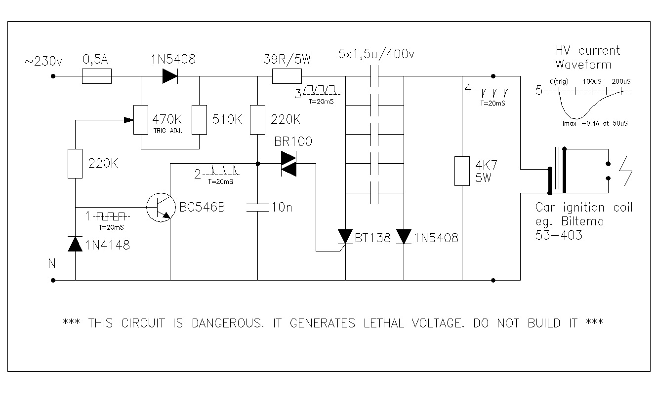
Specifications and schematic
- Input voltage 230vac 50/60Hz
- Output voltage -25kV pulse (T=200uS)
- Output peak current -0,4A
- Output pulse energy 0,3J
- Average output power 15W
- Trig event control at 180…270 deg.of phase
Theory
- During the positive swing of line voltage, the transistor BC546 is saturated via 470K trimmer and it’s 220K base resistor, and the capacitor bank of 5pcs 1,5uF capacitors in parallel, starts to charge via two 1N5408 diodes and 39R resistor, up to the peak line voltage SQR(2)*230v.
- When the line voltage starts to swing down, the capacitor bank will remain charged. In fact the bank voltage starts to drop via the swing comparator circuit’s 510K+470K and 220K resistors, but this effect is negligible, as R*C is over 1 sec.
- During the negative swing of the line voltage, at the phase angle set by swing comparator circuit’s 470K trimmer, the 1N4148 diode is driven forward biased, transistor BC546 reverse biased, and 10n capacitor starts charging via the 220K resistor.
- When the voltage of 10n capacitor exceeds the threshold voltage of diac BR100, the thyristor BT138 is trigged. The 5x1,5uF capacitor bank’s positive end is drawn to ground via the thyristor, and the negative voltage of the bank appears at the coil primary.
- The bank discharges through the primary, and high voltage is induced to the secondary.
- At the beginning of the next positive half cycle, the sequence is repeated.
The fuse and 39R resistor protect the thyristor in the case of erratic trigging. The diode 1N5408 and the 4k7 resistor both parallel to the primary, avoids ringing.
Operation
When powered up, the circuit generated fierce arc of 25mm length, between the coil secondary. The waveforms depicted in the schematic were observed. The output current was measured by letting the sparks ground via a 10ohm resistor, and measuring the voltage over the resistor with an oscilloscope. The trig event control was observed between ca.180…270 degrees of phase angle, by turning the 470K potentiometer. The sheet of paper placed between arc bursted immediately in flames.
Uses
- Spark gap trigging unit for marx generator or other pulse forming network. Two off-phase PFN’s could be used for powering a copper halide laser.
- Other high voltage experiments.
- Fuel ignition.