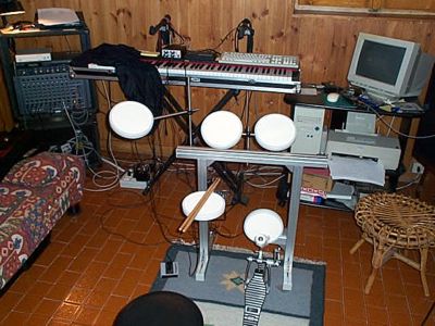
This circuit is a MIDI interface between drum pads and computer or hardware sequencer. Using this circuit you can hit pads with drumsticks and store the MIDI data in real time.
While this unit is much cheaper than commercial devices it does have some limitations:
- It provides MIDI data which has to be sent to a drum/synthesiser or sound module.
- The velocity byte is fixed at maximum volume and the drum selection and MIDI transmit channel are fixed at programming but can be edited afterwards in the sequencer software.
Circuit Description
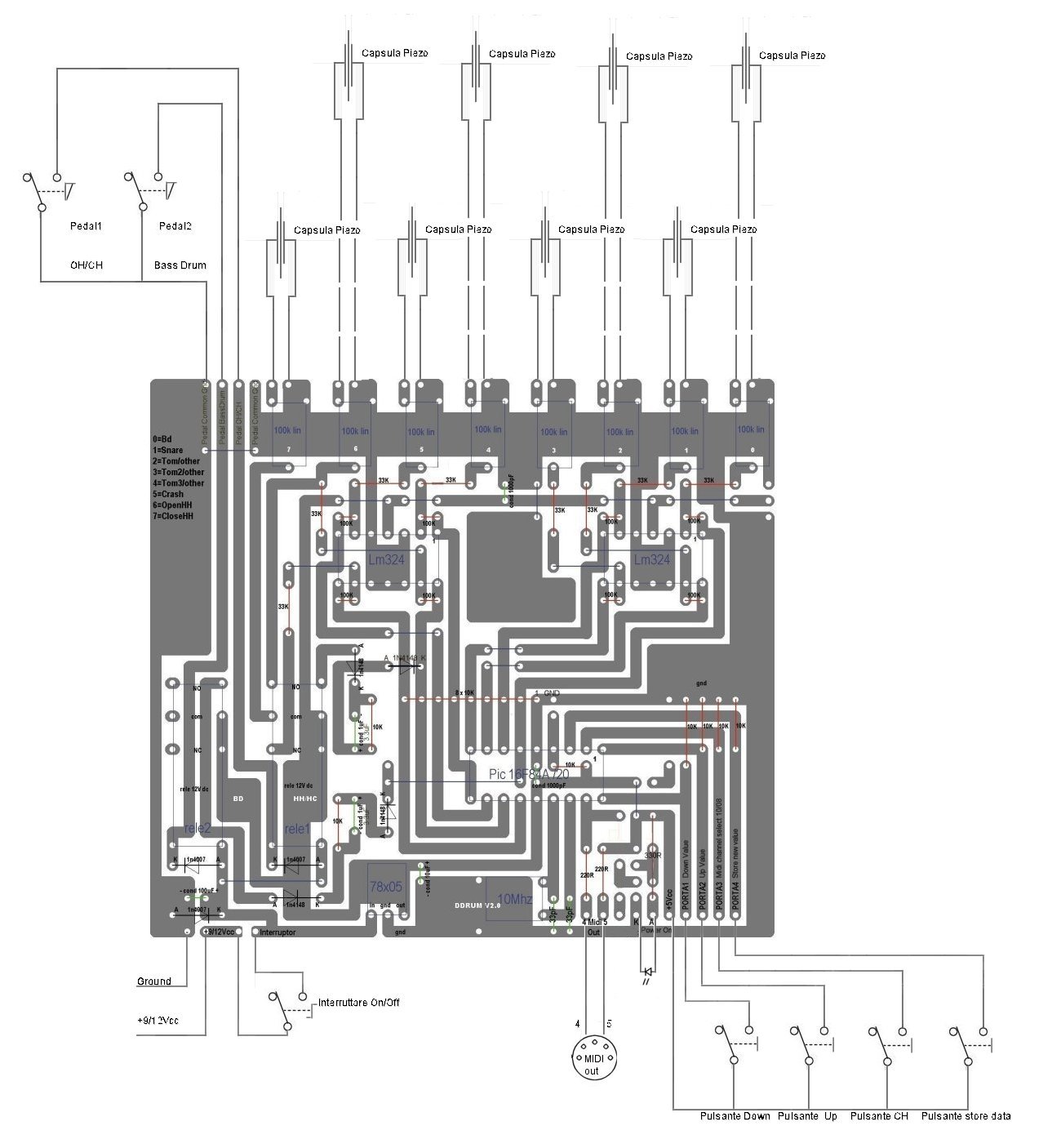
This circuit is based around the PIC 16C84 microcontroller which scans the inputs on RB0 to RB7 and when a high is detected the software transmits the equivalent note-on ( and then the MIDI note-off after a short delay) for the required drum sound on the MIDI output on RA0.
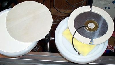
The inputs are provided by the piezo-electric transducers which can provide up to 40Vp-p depending on how hard they are hit. This voltage is reduced by the potential dividers R1 to R8 and R9 to R16 respectively. The values chosen reduce the input level by approximately 1/4 and is further reduced by internal clamping inside the microcontroller. If different transducers are used on the input then the potential dividers may need to be adjusted. Note that the inputs float high so the resistor values R9 to R16 need to be reasonably low so that when the microcontroller software scans the inputs it reads them all as low, with no transducer triggered. Also the maximum input continuous injection current into an I/O is specified as +/- 500uA, although it will sustain larger currents (>100mA) for short periods of time.
The timing is generated from the 10Mhz crystal and associated capacitors C1 and C2. The MIDI output is fed to the 180 degree 5-pin DIN socket via two 220R resistors which provide the required 10mA current loop. The power supply is a standard arrangement using a 9V-0-9V centre tapped transformer which is rectified by diodes D1 and D2 smoothed by C3 and regulated to 5V by IC2.
This MIDI box has 4 buttons:
- UP: select previous sound for selected pad*.
- DOWN: select next sound for selected pad*.
- MEM: save the current configuration to flash memory.
- MIDI: change between MIDI channel 10 and 8.
* To select a pad you must hit it.
PIC Software
Download the archive containing the PIC software.
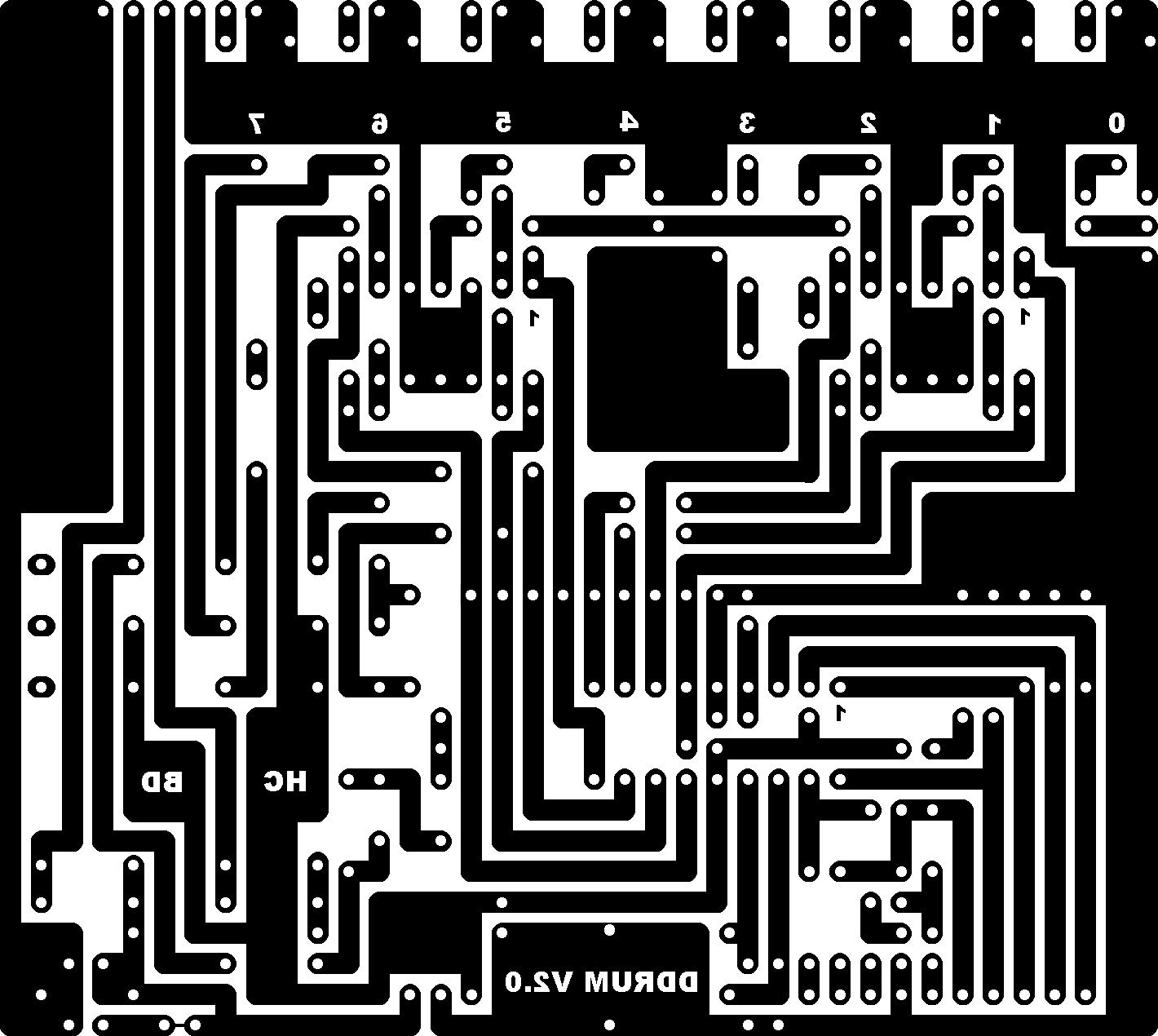
PCB schema
Components view
Components list
- 8 100 KOhm resistors
- 8 33 KOhm resistors
- 13 10 KOhm resistors
- 2 220 Ohm resistors
- 1 330 Ohm resistors
- 8 100 KOhm Linear Trimmer
- 2 33 pF Capacitor
- 1 1000 pF Capacitor
- 1 100 uF Capacitor
- 1 10 uF Capacitor
- 1 pic16f84a/20 (cod RS379-2932)
- 1 10Mhz Quartz
- 1 7805 (5V voltage regulator)
- 2 lm324 (Op. Amp.)
- 4 1N4148 diode
- 3 1N4007 diode
- 2 Relais 12vcc double switch (e.g.: NAIS Matsushita jw2sn-dc12v cod RS178-2129 f/max commutazione=20Hz)
- 4 switch buttons (common open)
- 1 led power on
- 2 jack femmina 6mm per pedali
- 1 DIN180° connector (midi out)
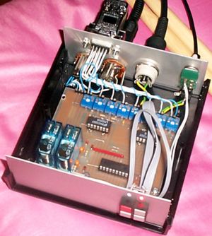
The unit can be mounted in any suitable enclosure and requires connections for a power cable, main switch, pads, pedals and MIDI OUT.
Basic MIDI Definitions
The MIDI data stream is a unidirectional asynchronous bit stream at 31.25Kbits/sec, with 10 bits transmitted per byte (a start bit, 8 data bits, and one stop bit). The MIDI interface on a MIDI instrument will generally include three different MIDI connectors, labeled IN, OUT, and THRU. The MIDI data stream is usually originated by a MIDI controller, such as a musical instrument keyboard, or by a MIDI sequencer. A MIDI controller is a device which is played as an instrument, and it translates the performance into a MIDI data stream in real time (as it is played). A MIDI sequencer is a device which allows MIDI data sequences to be captured, stored, edited, combined, and replayed. The MIDI data output from a MIDI controller or sequencer is transmitted via the devices MIDI OUT connector.
Each MIDI bit is transmitted for 32uS and so the timing is fairly critical and in the software this is achieved by timing loops which are accurate to the fundamental frequency of the 10Mhz crystal divided by four which is 0.25uS. The Real Time Clock Counter (RTCC) would not be as accurate for the MIDI transmission of 31.25Kbits/sec because of the overheads associated with the operation of the timing overflow and interrupt routines, but obviously works fine for lower baud rates.
Sources
- AleX [mailto:underjennifer@yahoo.com underjennifer@yahoo.com](/mailto:underjennifer@yahoo.com_underjennifer@yahoo.com)
- MIDI Hardware Kits